Machining program compensation for wiper SW/FW insert
Additional information on offsetting -SW / -FW wiper inserts
Compensations①, ④ Tool offsets (Compensations for X- and Z-axis)
Why need to offset ? Ex. When using DNMG150412
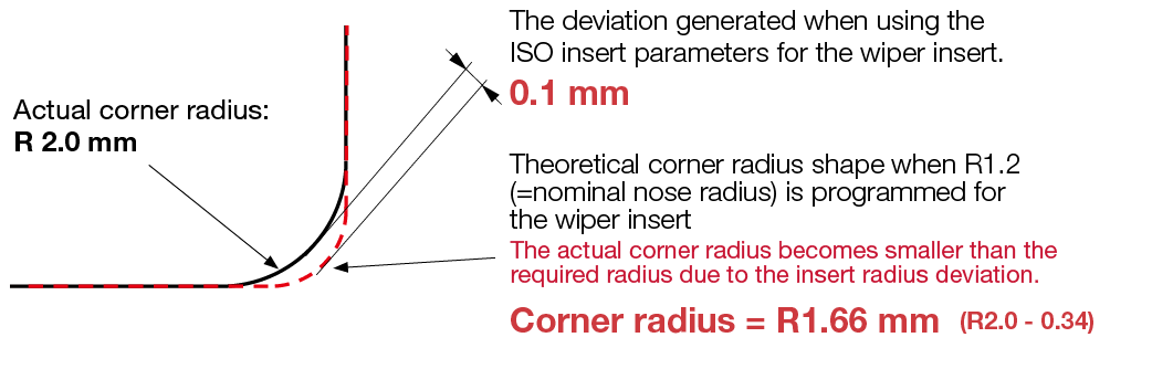
The wiper insert does not provide the exact corner radius. A deviation from the standard nose radius shape as shown below will always occur when going into a corner. An additional program adjustment is, therefore, required to achieve the correct corner radius or tapered surface dimension on the workpiece.
Wiper insert
Nominal nose radius
Before offset
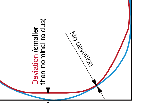
Wiper nose radius' contour is slightly smaller than the nominal radius.
⇒The nose radius profile deviates from the required corner radius, thus the actual corner profile will be incorrect.
After offset
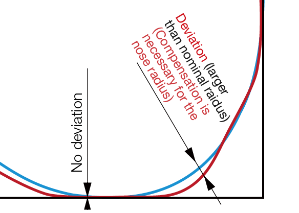
Wiper nose radius' contour is partially larger than the nominal radius.
⇒No compensations necessary for ID, OD, or face turning. Meanwhile, due to these deviations, compensations to the NC program are necessary when turning corners and tapered surfaces for the correct workpiece dimensions.
Compensations③, ⑥Program compensation for corner radii
(proceed after ①,④)
Compensation for corner radius Ex. When using DNMG150412
Example: to machine a corner radius = R2.0 mm, using insert nose radius = R1.2 mm.
For standard ISO insert: DNMG150412-**
Input R0.8 for G2 or G3 (circular interpolation) to compensate the nose radius deviation.
Wiper insert
For wiper insert: DNMG150412-SW/-FW
Input R1.14 (= R1.2 + 0.34 from the list) for the nose radius, instead of R0.8, to compensate the nose radius deviation.