Machining program compensation for wiper SW/FW insert
Compensations for DNMG / TNMG -SW / -FW
Compensations④,⑥ Internal, External, Face turning, corner radius
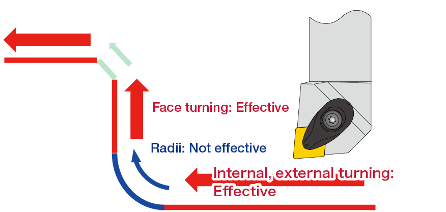
Compensate the NC program as described in ④,⑥ below.
Compensations④ Tool offsets (Compensations for X- and Z-axis)
Match the insert approach angle and the insert style to find the value and compensate the machining program for the insert radius.
*This compensation procedure will not be necessary if the insert is compensated with the built-in tool presetter after insert replacement.
| Nose Radius |
X-axis direction |
Z-axis direction |
|---|---|---|
| R0.4 | 0.24 | 0.03 |
| R0.8 | 0.23 | 0.04 |
| R1.2 | 0.12 | 0.03 |
| Nose Radius |
X-axis direction |
Z-axis direction |
|---|---|---|
| R0.4 | 0.24 | 0.04 |
| R0.8 | 0.21 | 0.05 |
| R1.2 | 0.16 | 0.04 |
| Nose Radius |
X-axis direction |
Z-axis direction |
|---|---|---|
| R0.4 | 0.24 | 0.02 |
| R0.8 | 0.21 | 0.02 |
| R1.2 | 0.15 | 0.02 |
| Nose Radius |
X-axis direction |
Z-axis direction |
|---|---|---|
| R0.4 | 0.02 | 0.24 |
| R0.8 | 0.02 | 0.21 |
| R1.2 | 0.02 | 0.15 |
Compensations⑥ Program compensation for corner radii (proceed after ④)
To achieve the correct corner radius dimension on the workpiece, compensate the tool position, using the values listed below for respective insert styles.
| Nose Radius |
Deviation on the corner radius |
Compensate radius by |
|---|---|---|
| R0.4 | 0 | 0 |
| R0.8 | 0.02 | +0.20 |
| R1.2 | 0.10 | +0.34 |
| Nose Radius |
Deviation on the corner radius |
Compensate radius by |
|---|---|---|
| R0.4 | 0 | 0 |
| R0.8 | 0.03 | +0.13 |
| R1.2 | 0.11 | +0.36 |
| Nose Radius |
Deviation on the corner radius |
Compensate radius by |
|---|---|---|
| R0.4 | 0 | 0 |
| R0.8 | 0.02 | +0.15 |
| R1.2 | 0.09 | +0.38 |